With the ongoing evolution of the construction machinery coating industry and the escalating environmental standards worldwide, the environmental and energy-saving advantages of powder coating technology in the construction machinery sector have become increasingly apparent. Consequently, numerous construction machinery manufacturers have established powder coating production lines.
In practical applications, powder coating offers high construction efficiency, low VOC emissions, and exceptional coating performance. Notably, it significantly reduces VOC emissions, eliminating the need for large waste gas treatment equipment and thereby reducing construction and operational costs. However, due to the characteristics of engineering machinery spraying tasks, the cooling method post-powder solidification has emerged as a critical issue limiting production line operations.
1. Characteristics of Engineering Machinery Powder Solidification
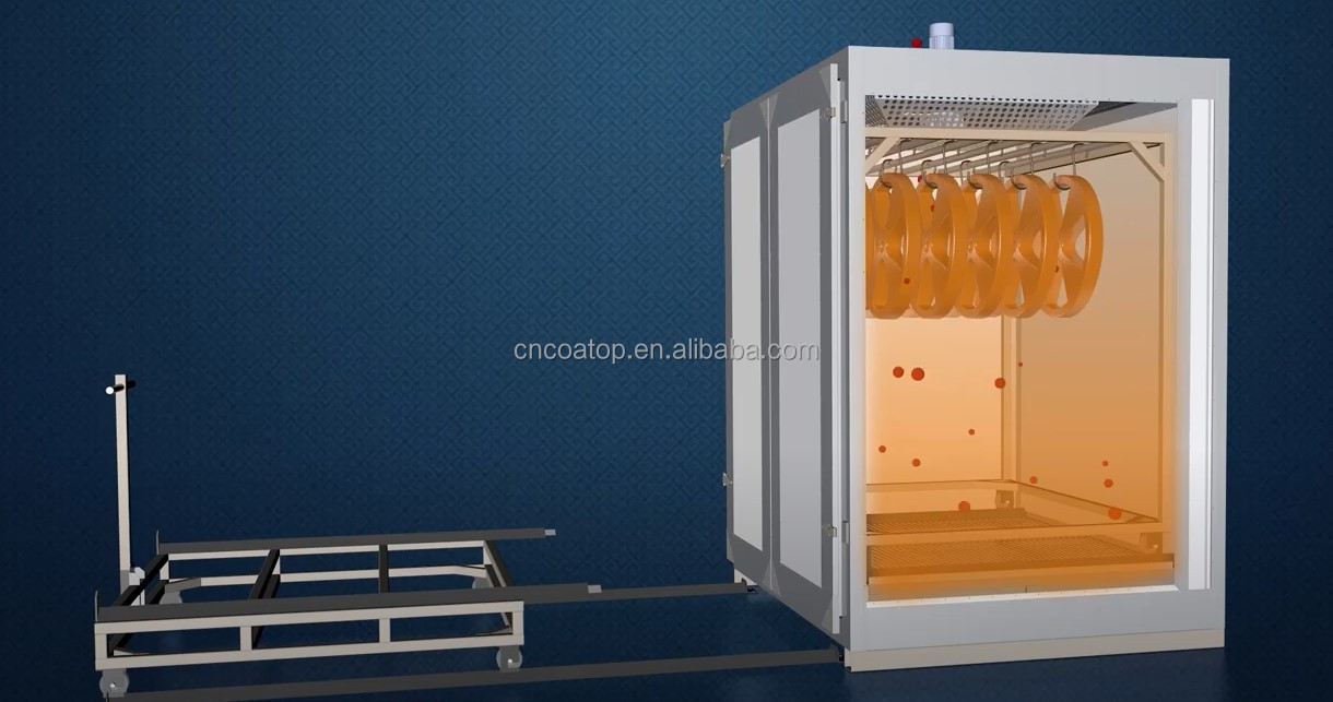
Powder coating has progressed from small structural parts and thin plate components to larger structural components in the engineering machinery field. Today, there's an increasing utilization of large structural components. Compared to small parts and thin plates, large structural parts, typically welded from thick plates and shaped steel, exhibit more pronounced characteristics. These parts often have steel plate thicknesses ranging from 10 to 20 mm, with some exceeding 20 mm. Due to their greater thickness and heat absorption capacity, large structural parts require extended time for powder solidification and absorb more heat, posing challenges for subsequent cooling processes. Firstly, powder solidification typically requires elevated temperatures (usually above 200°C), making rapid cooling unfeasible. Secondly, the cooling section typically employs cold air blowing to expedite surface heat dissipation. However, due to the thick plates of large structural parts, internal temperature reduction relies on conductive heat dissipation through the base material, leading to "heat recovery" phenomena. After cooling to the target temperature, the workpiece reheats in the buffer zone, preventing unloading.

2. Design Principles of the Curing Furnace Cooling Section
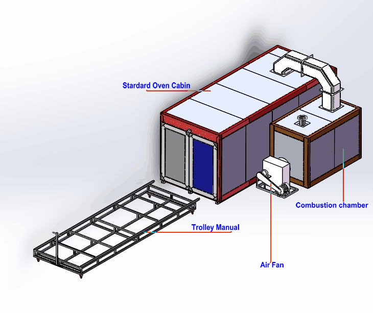
Post-drying cooling section designs typically aim for achieving room temperature cooling. Surface temperature recovery from the buffer to the unloading area should not exceed 10°C. Cooling duration significantly impacts effectiveness. Typically, in the lengthy production units of engineering machinery coating lines, the cooling section spans 2 to 3 stations, with cooling times ranging from 30 to 45 minutes. The forced cooling section comprises a chamber body, air supply and exhaust devices, air supply and exhaust ducts, and blower hoods. In the construction machinery industry, external air cooling is predominantly utilized. This method involves filtering outdoor air through air supply and exhaust device filters, then directing it via blower hoods for direct workpiece surface cooling without refrigeration devices. The robust cooling chamber (cooling section) generally consists of a profiled steel frame and a 50 mm thick composite sandwich rock wool board. The use of rock wool boards primarily aims to maintain consistency with the drying room appearance. Alternatively, if appearance consistency is unnecessary, materials like galvanized sheets or aluminized sheets can be used. The forced cooling chamber's blower hood features an adjustable high-speed air outlet nozzle. Typically, the nozzle outlet wind speed is about 15 m/s, air supply and exhaust duct wind speeds range from 8 to 12 m/s, and the room air exchange rate usually reaches 6 times per minute, potentially increased for enhanced cooling effects. The air supply and exhaust device constitutes the core component of the forced cooling room. Our company, Qingdao Jieruixin Machinery & Technology Co., Ltd., offers customized solutions for this equipment. This equipment filters outdoor air through high-efficiency filters (typically not lower than F5 filtration level) before directing it into the room via blowers, simultaneously expelling hot air. The equipment room employs a double-layer steel structure, internally lined with galvanized steel plates, externally with corrugated galvanized plates, and filled with thermal insulation cotton, providing an aesthetically pleasing and structurally sound solution.

3. Strategies to Improve Cooling Effectiveness
3.1 Increase Air Volume
Forced cooling chambers generally employ direct external air for cooling. This design, sensitive to external temperatures, benefits from increasing nozzle wind speeds to accelerate airflow over the workpiece surface, enhancing cooling efficiency and reducing cooling times. For instance, if the nozzle design air speed is 14 m/s, increasing the air supply volume to 16 m/s significantly enhances cooling speed. In some modified setups, fan pulleys can be replaced, fan impeller speeds increased, and cooling section fan design margins utilized to boost air supply volumes, achieving accelerated nozzle wind speeds.
3.2 Optimize Buffer Area Usage
Typical buffer area methods for addressing heat recovery involve allowing natural workpiece heat dissipation into the workshop environment. This approach raises temperatures in workshop areas, reducing the overall working environment's efficiency due to inadequate heat dissipation means. Addressing these shortcomings involves increasingly adopting closed buffer areas, paired with exhaust fans (negative pressure or axial flow fans) to maintain workpiece surface airflow speeds while preventing dissipated heat from affecting production environments.
3.3 Enhance Heat Exchange Medium Performance
Cooling section designs traditionally direct air onto workpiece surfaces to extract heat and achieve cooling. During this process, increased workpiece surface airflow rates enhance heat removal. However, due to air's low specific heat capacity, heat removal per unit volume remains limited. Furthermore, elevated air temperatures further diminish heat extraction capacity. Thus, replacing the heat exchange medium to increase specific heat capacity enhances heat removal efficiency per unit volume, thereby improving cooling section effectiveness.
Water, with its high specific heat capacity, serves as an economical heat exchange medium. Accordingly, incorporating atomizers into air supply and exhaust devices allows water atomization. The resulting air-water mist mixture uniformly blown onto workpiece surfaces enhances cooling efficiency by leveraging water mist evaporation for substantial heat removal. While this method increases construction and operational costs, it finds limited use in the construction machinery industry, typically where no buffer area post-cooling necessitates rapid workpiece release.
Qingdao Jieruixin Machinery & Technology Co., Ltd. draws upon extensive installation experience to offer professional spray production line solutions. Please feel free to inquire for further details!


